
DynamicCheckValve#
Copyright © EDF 2002 - 2026#
ThermoSysPro Version 4.2#
This component model is documented in Sect. 13.12 of the ThermoSysPro book.
Dynamic check valve#
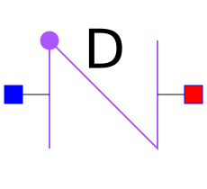
The dynamic check valve is modeled as a control valve which position is controlled by the flow through the clapper aperture.
The inertia of the movement of the clapper is taken into account, contrary to the check valve.
The model presented here only accounts for clapper check valves.
Modelica component model#
The equations mentioned below are implemented in the component DynamicCheckValve, located in the WaterSteam.PressureLosses sub-library.
This component has 2 connectors:
C1: fluid inlet,
C2: fluid outlet.
Nomenclature#
Symbol |
Description |
Unit |
Definition |
Modelica name |
|---|---|---|---|---|
\(A\) |
Clapper hydraulic area |
\(\mathrm{m}^{2}\) |
A |
|
\(C_{\mathrm{f}}\) |
Friction torque acting on the clapper |
\(\mathrm{N} \mathrm{m}\) |
Cf |
|
\(C_{\mathrm{h}}\) |
Hydraulic torque acting on the clapper |
\(\mathrm{N} \mathrm{m}\) |
Ch |
|
\(C_{\mathrm{s}}\) |
Spring torque acting on the clapper |
\(\mathrm{N} \mathrm{m}\) |
- |
|
\(C_{\mathrm{t}}\) |
Total torque acting on the clapper |
\(\mathrm{N} \mathrm{m}\) |
Ct |
|
\(C_{\mathrm{v}}\) |
Flow coefficient of the valve |
U.S. [USG/min] |
Cv |
|
\(C_{\mathrm{w}}\) |
Weight torque acting on the clapper |
\(\mathrm{N} \mathrm{m}\) |
Cp |
|
\(g\) |
Gravity constant |
\(\mathrm{m} / \mathrm{s}^{2}\) |
g_n |
|
\(h\) |
Fluid specific enthalpy |
\(\mathrm{J} / \mathrm{kg}\) |
h |
|
\(J\) |
Clapper moment of inertia |
\(\mathrm{kg} \mathrm{m}^{2}\) |
J |
|
\(K_{1}\) |
Clapper friction law coefficient |
\(-\) |
Kf1 |
|
\(K_{2}\) |
Clapper friction law coefficient |
\(-\) |
Kf2 |
|
\(m\) |
Fluid mass flow rate through the valve |
\(\mathrm{kg} / \mathrm{s}\) |
Q |
|
\(M\) |
Clapper mass |
\(\mathrm{kg}\) |
m |
|
\(n\) |
Clapper friction law exponent |
\(-\) |
n |
|
\(P_{\mathrm{i}}\) |
Fluid pressure at the valve inlet |
\(\mathrm{Pa}\) |
C1.P |
|
\(P_{\mathrm{o}}\) |
Fluid pressure at the valve outlet |
\(\mathrm{Pa}\) |
C2.P |
|
\(r\) |
Clapper radius |
\(\mathrm{m}\) |
\(\frac{A}{\pi}\) |
r |
\(\Delta P\) |
Fluid pressure loss between the inlet and the outlet |
\(\mathrm{Pa}\) |
\(P_{\mathrm{i}}-P_{\mathrm{o}}\) |
deltaP |
\(\theta\) |
Clapper aperture angle |
\(\mathrm{rad}\) |
theta |
|
\(\theta_{\min }\) |
Minimum clapper aperture angle (valve fully closed) |
\(\mathrm{rad}\) |
theta_min |
|
\(\theta_{\max }\) |
Maximum clapper aperture angle (valve fully open) |
\(\mathrm{rad}\) |
theta_max |
|
\(\rho\) |
Fluid density |
\(\mathrm{kg} / \mathrm{m}^{3}\) |
rho |
|
\(\rho_{\text {water, } 60^{\circ} \mathrm{F}}\) |
Density of water at \(60^{\circ} \mathrm{F}\left(15.5556^{\circ} \mathrm{C}\right) .\) |
\(\mathrm{kg} / \mathrm{m}^{3}\) |
- |
|
\(\omega\) |
Clapper angular velocity |
\(\mathrm{rad} / \mathrm{s}\) |
omega |
|
\(\Omega\) |
Valve position |
\(-\) |
\(1-\cos (\theta)\) |
Ouv |
Governing equations#
Static momentum balance equation#
Validity domain:
\(\forall \dot{m}\) and \(C_{\mathrm{v}} \geq 0\). For \(C_{\mathrm{v}}=0, \Delta P\) must be defined.
Mathematical formulation:
Comments:
This equation is the same as the control valve’s \(C_{\mathrm{v}}=f_{v}(\Omega)\) where \(f_{v}\) is the valve characteristic.
Clapper equation#
Validity domain:
\( \theta_{\min} \leq \theta \leq \theta_{\max} \)
Mathematical formulation:
Comments:
The angular velocity and acceleration are set to zero when the clapper hits
the mechanical stops. The equal sign is replaced by \(\leq\) or \(\geq\) in the transition conditions \(\theta=\theta_{\min }\) and \(\theta=\theta_{\max }\) because equal signs are not recognized by solvers to compare real values.
References#
El Hefni, Baligh and Bouskela, Daniel (2019). Modeling and Simulation of Thermal Power Plants with ThermoSysPro, sect. 13.1. Springer Nature Switzerland AG.