
CombustionTurbine#
Copyright © EDF 2002 - 2026#
ThermoSysPro Version 4.2#
This component model is documented in Sect. 11.4 of the ThermoSysPro book.
Combustion turbine#
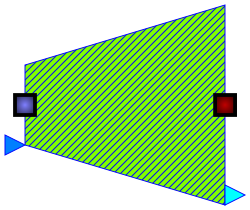
A combustion turbine, also called gas turbine, is a type of internal combustion engine. The main elements common to all gas turbines are an upstream rotating gas compressor, a combustor and a downstream turbine on the same shaft as the compressor.
In this model, the hot fluid flow is assumed steady-state and supersonic.
Modelica component model#
The equations mentioned below are implemented in the component CombustionTurbine, located in the FlueGases.Machines sub-library.
The component has 4 connectors:
Ce: flue gases at the inlet,
Cs: flue gases at the outlet,
CompressorPower: compressor power input,
MechPower: mechanical power output.
Nomenclature#
Symbol |
Description |
Unit |
Definition |
Modelica name |
|---|---|---|---|---|
\(h_{\mathrm{i}}\) |
Fluid specific enthalpy at the inlet |
\(\mathrm{J} / \mathrm{kg}\) |
He |
|
\(h_{\mathrm{is}}\) |
Fluid specific enthalpy after the isentropic expansion |
\(\mathrm{J} / \mathrm{kg}\) |
His |
|
\(h_{\mathrm{o}}\) |
Fluid specific enthalpy at the outlet |
\(\mathrm{J} / \mathrm{kg}\) |
Hs |
|
\(\dot{m}\) |
Fluid mass flow rate |
\(\mathrm{kg} / \mathrm{s}\) |
Q |
|
\(\dot{m}_{\mathrm{cor}}\) |
Corrected mass flow rate (mass flow rate parameter) |
\(-\) |
Qred |
|
\(P_{\mathrm{i}}\) |
Fluid pressure at the inlet |
\(\mathrm{Pa}\) |
Pe |
|
\(P_{\mathrm{o}}\) |
Fluid pressure at the outlet |
\(\mathrm{Pa}\) |
Ps |
|
\(W_{\mathrm{c}}\) |
Compressor power (negative value) |
\(\mathrm{W}\) |
Wcp |
|
\(W_{\mathrm{m}}\) |
Mechanical power |
\(\mathrm{W}\) |
Wmech |
|
\(W_{\mathrm{t}}\) |
Turbine power (total power) |
\(\mathrm{W}\) |
Wturb |
|
\(X\) |
Ratio between the actual and nominal expansion rate |
\(-\) |
\(\pi / \pi_{n}\) |
Xtau |
\(\eta_{\mathrm{is}}\) |
Isentropic efficiency |
\(-\) |
is_eff |
|
\(\eta_{\mathrm{n}}\) |
Nominal isentropic efficiency |
\(-\) |
is_eff_n |
|
\(\pi\) |
Expansion rate |
\(-\) |
\(P_{\mathrm{o}} / P_{\mathrm{i}}\) |
tau |
\(\pi_{\mathrm{n}}\) |
Nominal expansion rate |
\(-\) |
tau_n |
Governing equations#
Fluid specific enthalpy at the outlet#
Validity domain:
\(\forall h_{\mathrm{i}}\)
Mathematical formulation:
Comments:
Isentropic efficiency#
Validity domain:
\(X>0\)
Mathematical formulation:
Comments:
\(f_{\eta_{\mathrm{is}}}(X)\) is the turbine map expressed as a polynomial function of \(X\).
Total turbine power#
Validity domain:
\(\forall \dot{m}\)
Mathematical formulation:
Comments:
Mechanical power#
Validity domain:
\(\forall \dot{m}\)
Mathematical formulation:
Comments:
The mechanical power produced by the shaft of the electricity generator is the total turbine power minus the power used by the compressor (counted negatively).
Mass flow rate#
Validity domain:
\(\forall P_{i}\) and \(\forall T_{\mathrm{i}}\)
Mathematical formulation:
Comments:
This equation calculates the mass flow rate from the corrected mass flow rate provided by the user.
References#
El Hefni, Baligh and Bouskela, Daniel (2019). Modeling and Simulation of Thermal Power Plants with ThermoSysPro, sect. 11.4. Springer Nature Switzerland AG.