
Mixer3#
Copyright © EDF 2002 - 2026#
ThermoSysPro Version 4.2#
This component model is documented in Sect. 14.7 of the ThermoSysPro book.
Mixer3#
This static model describes the mixing of an adiabatic single-phase fluid or two-phase fluid with homogeneous flow in the mixer volume.
Modelica component model#
The equations mentioned below are implemented in the component Mixer3, located in the WaterSteam.Junctions sub-library.
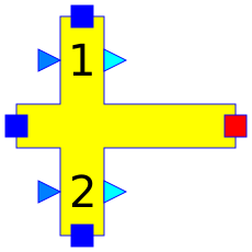
This component has 8 connectors:
Ce1: first fluid inlet,
Ce2: second fluid inlet,
Ce3: third fluid inlet,
Cs: fluid outlet,
Ialpha1: extraction coefficient imposing the fraction Ce1.Q/Cs.Q,
Ialpha2: extraction coefficient imposing the fraction Ce2.Q/Cs.Q,
Oalpha1: value of Ce1.Q/Cs.Q,
Oalpha2: value of Ce2.Q/Cs.Q.
If the connector Ialpha.x is not connected, then the fraction Cex.Q/Cs.q is not imposed.
If the connector Ialpha.x is connected, then Oalphax=Ialphax.
Nomenclature#
Symbol |
Description |
Unit |
Definition |
Modelica name |
|---|---|---|---|---|
\(h_{\mathrm{i}_{1}}\) |
Specific enthalpy of the fluid at inlet 1 |
\(\mathrm{J} / \mathrm{kg}\) |
Ce1.h |
|
\(h_{\mathrm{i}_{2}}\) |
Specific enthalpy of the fluid at inlet 2 |
\(\mathrm{J} / \mathrm{kg}\) |
Ce2.h |
|
\(h_{\mathrm{i}_{3}}\) |
Specific enthalpy of the fluid at inlet 3 |
\(\mathrm{J} / \mathrm{kg}\) |
Ce3.h |
|
\(h_{\mathrm{o}}\) |
Specific enthalpy of the fluid at the outlet of the mixer |
\(\mathrm{J} / \mathrm{kg}\) |
Cs.h |
|
\(m_{\mathrm{i}_{1}}\) |
Mass flow rate of the fluid at inlet 1 |
\(\mathrm{kg} / \mathrm{s}\) |
Ce1.Q |
|
\(\dot{m}_{\mathrm{i}_{2}}\) |
Mass flow rate of the fluid at inlet 2 |
\(\mathrm{kg} / \mathrm{s}\) |
Ce2.Q |
|
\(\dot{m}_{\mathrm{i}_{3}}\) |
Mass flow rate of the fluid at inlet 3 |
\(\mathrm{kg} / \mathrm{s}\) |
Ce3.Q |
|
\(\dot{m}_{\mathrm{o}}\) |
Mass flow rate of the fluid at the outlet |
\(\mathrm{kg} / \mathrm{s}\) |
Cs.Q |
|
\(\alpha_{1}\) |
Extraction coefficient for inlet 1 (output of the model) |
\(-\) |
\(\frac{\dot{m}_{\mathrm{i}_{l}}}{\dot{m}_{\mathrm{o}}}\) |
|
\(\alpha_{2}\) |
Extraction coefficient for inlet 2 (output of the model) |
\(-\) |
\(\frac{\dot{m}_{\mathrm{i}_{2}}}{\dot{m}_{\mathrm{o}}}\) |
|
\(\alpha_{\mathrm{i}_{1}}\) |
Mass fraction coefficient for inlet 1 |
\(-\) |
Ialpha1.signal |
|
\(\alpha_{\mathrm{i}_{2}}\) |
Mass fraction coefficient for inlet 2 |
\(-\) |
Ialpha2.signal |
Governing equations#
Static mass balance equation#
Validity domain:
\(\forall \dot{m}\)
Mathematical formulation:
Comments:
\(\dot{m}_{\mathrm{i}_{l}}\) and \(\dot{m}_{\mathrm{i} 2}\) can be defined as a fraction of the output mass flow rate:
$\(\dot{m}_{\mathrm{i}_{l}}=\alpha_{\mathrm{i}_{l}} \cdot \dot{m}_{\mathrm{o}} \quad \text{and} \quad \dot{m}_{\mathrm{i}_{2}}=\alpha_{\mathrm{i}_{2}} \cdot \dot{m}_{\mathrm{o}}\)$
This enables the computation of the mass flow rates at the inlets from the outlet mass flow rate.
Static energy balance equation#
Validity domain:
\(\exists \dot{m}\) such that \(\dot{m} \neq 0\)
Mathematical formulation:
Comments:
This equation is valid if some mass flow rates are non-zero. Otherwise, the mixing specific enthalpy is undefined.
References#
El Hefni, Baligh and Bouskela, Daniel (2019). Modeling and Simulation of Thermal Power Plants with ThermoSysPro, sect. 14.7. Springer Nature Switzerland AG.