
DynamicOnePhaseFlowShell#
Copyright © EDF 2002 - 2026#
ThermoSysPro Version 4.2#
This component model is documented in Sect. 9.4.3 of the ThermoSysPro book.
Nota: component model name in title of Sect. 9.4.3.3 in book is incorrectly given as DynamicTwoPhaseFlowShell, instead of DynamicOnePhaseFlowShell.
Dynamic one phase flow shell#
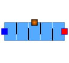
This component is a heat exchanger shell.
The space between the tube bundle and the shell is filled with liquid water, which exchanges heat with the fluids in the tubes.
The shell model represents the fluid circulating outside the tube bundle and the thermal exchange between fluid and tubes.
It can be used for single- and two-phase flow.
Modelica component model#
The equations mentioned below are implemented in the component DynamicOnePhaseFlowShell, located in the WaterSteam.HeatExchangers sub-library.
This component has 3 connectors:
C1: fluid inlet,
CTh: thermal port,
C2: fluid outlet.
Nomenclature#
Symbol |
Description |
Unit |
Definition |
Modelica name |
|---|---|---|---|---|
\(A\) |
Cross-sectional area of the fluid flow that is perpendicular to the pipes |
\(\mathrm{m}^{2}\) |
\(\pi \cdot D_{s}^{2} / 4-N_{\mathrm{t}} \cdot \pi \cdot D_{\mathrm{e}}^{2} / 4\) |
A |
\(A_{s}\) |
Maximum cross-sectional area of the fluid that is parallel to the pipes |
\(\mathrm{m}^{2}\) |
\(D_{\mathrm{s}} \cdot L_{\mathrm{c}} \cdot\left(\frac{S_{\mathrm{L}}-D_{\mathrm{e}}}{S_{\mathrm{L}}}\right)\) |
As |
\(c_{p, l, i}\) |
Specific heat capacity of the liquid phase for cell \(i\) |
\(\mathrm{J} / \mathrm{K} / \mathrm{kg}\) |
cp[i] |
|
\(D_{\mathrm{e}}\) |
External diameter of one pipe |
\(\mathrm{m}\) |
De |
|
\(D_{\mathrm{s}}\) |
Shell internal diameter |
\(\mathrm{m}\) |
Ds |
|
\(L_{\mathrm{c}}\) |
Distance between two plates in the shell (support plate spacing in the cooling zone) |
\(\mathrm{m}\) |
B |
|
\(Pr_{l, i}\) |
Prandtl number of the liquid phase for thermal cell \(i\) |
\(\frac{c_{p, 1, i} \cdot \mu_{l, i}}{\lambda_{l, i}}\) |
Pr[i] |
|
\(q_{S, i:i+1}\) |
Surface mass flow rate for hydraulic cell \(i: i+1\) |
\(\mathrm{kg} / \mathrm{s} / \mathrm{m}^{2}\) |
\(\frac{\dot{m}_{i:i+1}}{A_{s}}\) |
- |
\(R e_{l, i:i+1}\) |
Reynolds number of the liquid phase for hydraulic cell \(i: i+1\) |
\(-\) |
Re2[i] |
|
\(R e_{l, i}\) |
Reynolds number of the liquid phase for thermal cell \(i\) |
\(-\) |
Re1[i] |
|
\(S_{\mathrm{L}}\) |
Longitudinal step |
\(\mathrm{m}\) |
dc |
|
\(S_{\mathrm{T}}\) |
Transverse step |
\(\mathrm{m}\) |
- |
|
\(\theta\) |
Average bend angle (pipe triangular step) |
Degree |
- |
|
\(\lambda_{l, i}\) |
Liquid thermal conductivity for thermal cell \(i\) |
\(\mathrm{W} / \mathrm{m} / \mathrm{K}\) |
k[i] |
|
\(\mu_{l, i:i+1}\) |
Liquid dynamic viscosity for hydraulic cell \(i: i+1\) |
Pa \(\mathrm{s}\) |
mu2[i] |
|
\(\mu_{l\mathrm{T}, i:i+1}\) |
Liquid dynamic viscosity at the wall temperature for hydraulic cell \(i: i+1\) |
Pa \(\mathrm{s}\) |
- |
|
\(\mu_{l, i}\) |
Liquid dynamic viscosity for thermal cell \(i\) |
Pa s |
mu1[i] |
Governing equations#
The shell equations are similar to the tube bundle heat exchanger (see Tube bundle heat exchanger, except the friction correlation in the momentum balance equations.
Dynamic momentum balance equations#
Validity domain:
\(\forall \dot{m}_{i:i+1}\) and \(400<R e_{l, i:i+1}<10^{6}\)|
Mathematical formulation:
Comments::
The friction coefficient \(\Lambda_{i}\) is computed using \(\Lambda_{i:i+1}=e^{0.576-0.19 \ln R_{e i, i t}+1}\).
The Reynolds number for the liquid phase is given by: \(R e_{l, i:i+1}=\frac{q_{S, i:i+1} \cdot D_{\mathrm{e}}}{\mu_{l, i:i+1}}\).
Convective heat exchanged between the fluid and the wall#
Validity domain:
\(\forall T_{\mathrm{w}, i}\) and \(\forall T_{i}\)
Mathematical formulation:
Comments:
The convection heat transfer coefficient \(h_{\mathrm{c}, \mathrm{i}}\)between the fluid and the wall is computed using:
$\( h_{\mathrm{c}, \mathrm{i}}=\frac{\lambda_{l}}{D_{\mathrm{e}}} \cdot 0.5 \cdot R e_{l, i}^{0,507} \cdot P r_{l, i}^{0,33} \)\( for \)R e_{l, i}<2000$
$\( h_{\mathrm{c}, \mathrm{i}}=\frac{\lambda_{l}}{D_{\mathrm{e}}} \cdot 0.36 \cdot R e_{l, i}^{0,55} \cdot P r_{l, i}^{0,33} \cdot \left(\frac{\mu_{l, i}}{\mu_{\mathrm{Tr}, i}}\right)^{0,14}\)\( for \)2000<R e_{l, i}<10^{6}$
For the sake of simplicity, \(R e_{l, i}=R e_{l, i:i+1}\).
References#
El Hefni, Baligh and Bouskela, Daniel (2019). Modeling and Simulation of Thermal Power Plants with ThermoSysPro, sect. 9.4.3. Springer Nature Switzerland AG.